
Beyond Assembly: A Transparent Walkthrough of Our High-Reliability PCBA Process for Power Solutions
High-reliability applications like battery management systems (BMS) and power tools demand precise, repeatable, and controlled PCBA (Printed Circuit Board Assembly) processes. This guide provides a complete, end-to-end view of our PCBA workflow—from bare PCB to fully tested and programmed modules—covering critical controls, reproducible checks, common defects, and troubleshooting.
PCBA Process Overview
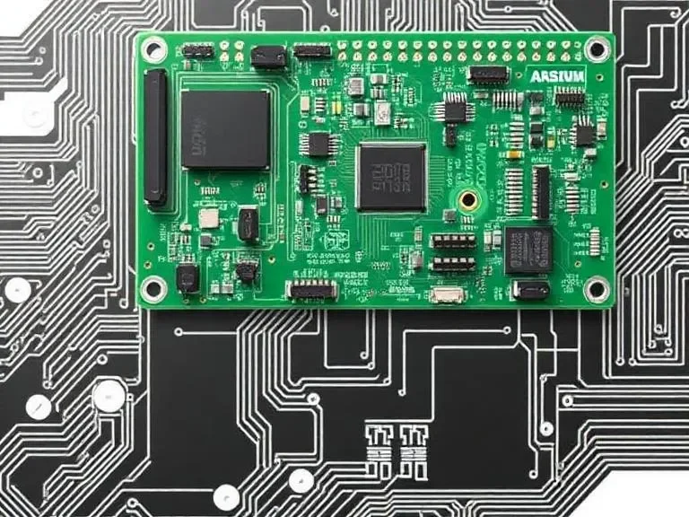
A PCBA is more than a populated board; it is a functional system module. The complete high-reliability PCBA workflow involves multiple integrated stages:
Incoming materials → Solder paste & stencil → SPI → Pick-and-place → Reflow soldering → AOI/X-ray → Through-hole/secondary operations → Rework & repair → Electrical testing (ICT/Flying probe & FCT) → Programming & calibration → Reliability screening/burn-in → Final inspection, marking & packing → Continuous process control & SPC.
Each stage has reproducible checks, inspection protocols, and traceability measures to ensure consistent quality. Safety, ESD compliance, and thermal management are overarching requirements at every step.
Safety First (Must-Read)
-
Enforce ESD protection at all stations (wrist straps, ionizers, grounded mats).
-
Treat thermal and process equipment as hazardous—operators must wear PPE and be trained.
-
Use current-limited and isolated supplies during power-up or debugging; stop immediately on smoke, odor, or excessive heat.
-
Follow chemical safety protocols for solder paste, flux, and cleaning agents, ensuring proper ventilation.
Step 1: Incoming Materials & Preparation (IQC & MSL Handling)
High-quality assemblies begin with controlled inputs. Verify PCB fabrication, component reels, solder paste lot, and stencil condition. For moisture-sensitive components, confirm MSL bake history and storage conditions. Inspect tape integrity, component count, and dimensions. Document and quarantine any deviations.
Key practices:
-
Check PCB surface for contamination or warping.
-
Validate component labels, lot numbers, and packaging integrity.
-
Confirm solder paste viscosity and temperature history.
-
Bake MSL-sensitive components per IPC/JEDEC guidelines before assembly.
Common defects at this stage: wrong component reels, mislabeling, PCB warping, expired solder paste.
Step 2: Solder Paste & Stencil Printing
Stencil printing deposits precise solder paste volumes onto PCB pads. Aperture geometry, snap-off distance, squeegee speed, and paste temperature affect wetting, bridging, and tombstoning.
Best practices:
-
Perform SPI (Solder Paste Inspection) on first articles and periodic sampling.
-
Stop the line if volume/area deviations occur.
-
Adjust aperture ratios and squeegee parameters to balance paste deposition.
Defect mitigation: bridging → reduce paste volume or tune profile; open joints → verify paste deposition and stencil alignment.
Step 3: Pick-and-Place (PnP) & Placement Accuracy
Vision-guided pick-and-place machines position components with tight X/Y/θ tolerances. First-article verification and daily feeder/spindle checks prevent misalignment.
Key checks:
-
Feeder and nozzle validation.
-
Vision alignment calibration.
-
Polarity and rotation verification on first boards.
Defect mitigation: misplacement → clean nozzles, check feeder orientation, re-teach machines.
Step 4: Reflow Soldering
Reflow soldering creates metallurgical joints in a controlled thermal profile: preheat, soak, ramp, peak, and cool. Thermocouple coupons validate profiles.
Critical parameters:
-
Peak temperature vs component tolerance.
-
Time above liquidus.
-
Ramp rates to avoid tombstoning or BGA voiding.
Defect mitigation: cold joints → adjust peak temperature or paste; tombstoning → balance thermal soak; BGA voids → adjust profile or consider N₂ atmosphere.
Step 5: Post-Reflow Inspection (AOI/X-ray)
Automated Optical Inspection (AOI) detects missing parts, polarity errors, tombstones, and visible solder defects. X-ray inspects hidden joints (BGAs, QFNs).
Best practices:
-
Compare to “golden board” baseline images.
-
Log failures for trend analysis.
-
Feed AOI/X-ray data back to stencil/paste/placement adjustments.
Step 6: Through-Hole, Selective Solder & Secondary Operations
Wave or hand-solder PTH components, dispense adhesives, or apply conformal coating as required. Verify visual appearance, solder fillet quality, and curing profiles.
Step 7: Rework & Repair
Certified operators perform controlled rework with documented procedures. Post-rework functional checks ensure process compliance.
Defect mitigation: pad lift → reduce heat/dwell time; misaligned rework → verify alignment before soldering.
Step 8: Electrical Testing — ICT/Flying Probe & FCT
-
ICT/Flying Probe: verify nets, passive values, shorts/opens.
-
FCT: simulate system-level behavior, firmware verification, and end-use scenarios.
Log all failures for root-cause analysis.
Step 9: Programming, Calibration & Verification
Use dedicated fixtures for in-circuit programming, sensor calibration, and EEPROM updates. Verify checksums/CRCs and perform golden-unit validation.
Step 10: Reliability Screening & Burn-In
High-reliability boards undergo thermal cycling, burn-in, vibration, or SIR testing. Controlled racks monitor current and temperature, and failure logs correlate with assembly lots.
Step 11: Final Inspection, Marking & Packing
OQC includes serial/label verification, MSL-controlled storage, and protective packing. Maintain traceability to assembly lot and key metrics (yield, AOI/X-ray statistics).
Step 12: Continuous Process Control & SPC
-
Monitor SPI pass rate, placement Cp/Cpk, AOI defect types, reflow profile variance, ICT first-pass yield, and FCT fail rate.
-
Drift triggers immediate containment, root-cause analysis, and corrective verification.
Common Defects & Troubleshooting
-
Solder bridging: excess paste → reduce volume or adjust profile.
-
Tombstoning: uneven paste → tune thermal soak.
-
Cold joints: low peak temperature → increase soak/peak or replace paste.
-
Misplacement/wrong parts: feeder misload → implement barcode checks.
-
BGA voiding: outgassing/profile issues → adjust profile or use N₂.
Stepwise troubleshooting: capture logs, isolate by stage, run first-article repeat, implement corrective action, verify with sample batch.
Maintenance & First-Article Practice
-
Conduct first-article verification after process changes.
-
Archive reflow coupons and AOI snapshots.
-
Schedule predictive maintenance for PnP heads, oven belts, and SPI optics.
Metrics for Continuous Improvement
Track FPY, defect density, mean time between feeder/nozzle faults, and rework hours per thousand boards. Use trends to prioritize Kaizen initiatives.
FAQ
Q: How to verify solder paste quality before reflow?
A: Use SPI, check volume/area on pads, confirm MSL bake status; deviations indicate potential open joints or bridging.
Q: How often should pick-and-place be verified?
A: First-article check post-nozzle/feeder change and daily SPC on X/Y/θ.
Q: How to detect reflow profile drift?
A: Thermocouple coupons for every oven change; compare Tpeak/time-above-liquidus vs golden profile ±5 °C.
Q: When is functional test mandatory?
A: Always for system-level verification, firmware, or end-use simulation when ICT/flying probe cannot fully test functionality.
Q: How to distinguish material, placement, or thermal defects?
A: Cross-reference SPI, feeder/nozzle logs, reflow coupon data, AOI/X-ray, and FCT results.
Q: Why burn-in/reliability screening?
A: Detects early failures in high-risk/high-cost products before shipment.
Conclusion — One-Line Takeaway + Immediate Actions
A robust PCBA process requires controlled paste, precise placement, reflow soldering, layered inspection, and reproducible checks. First-article verification is essential whenever process variables change.
Immediate actions:
-
Implement first-article verification for all process changes.
-
Archive AOI, SPI, and reflow data for traceability.
-
Monitor FPY and defect density trends to guide continuous improvement.