Learn About Lithium Battery Protective Boards (PCB/BMS)
This blog introduces the protective circuit board (PCB) or Battery Management System (BMS) used in lithium‑ion packs, explaining why it’s essential for cell safety, longevity, and overall pack reliability.

1. What Is a Battery PCB and How Does It Work?
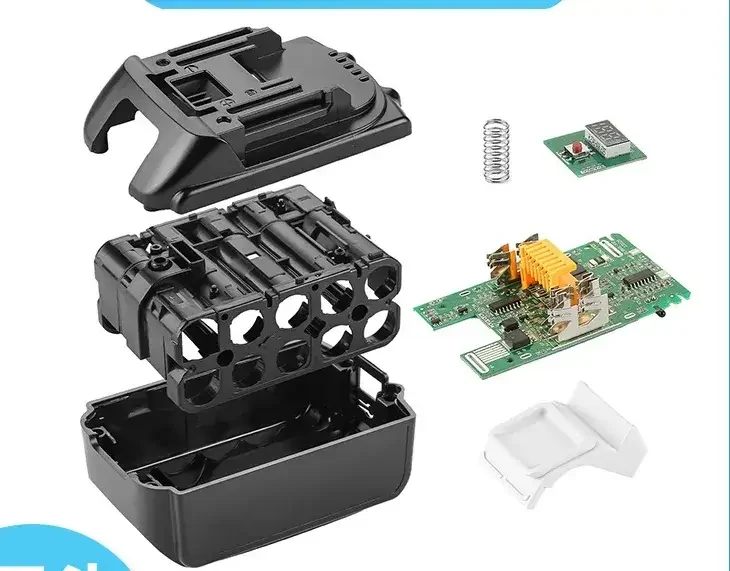
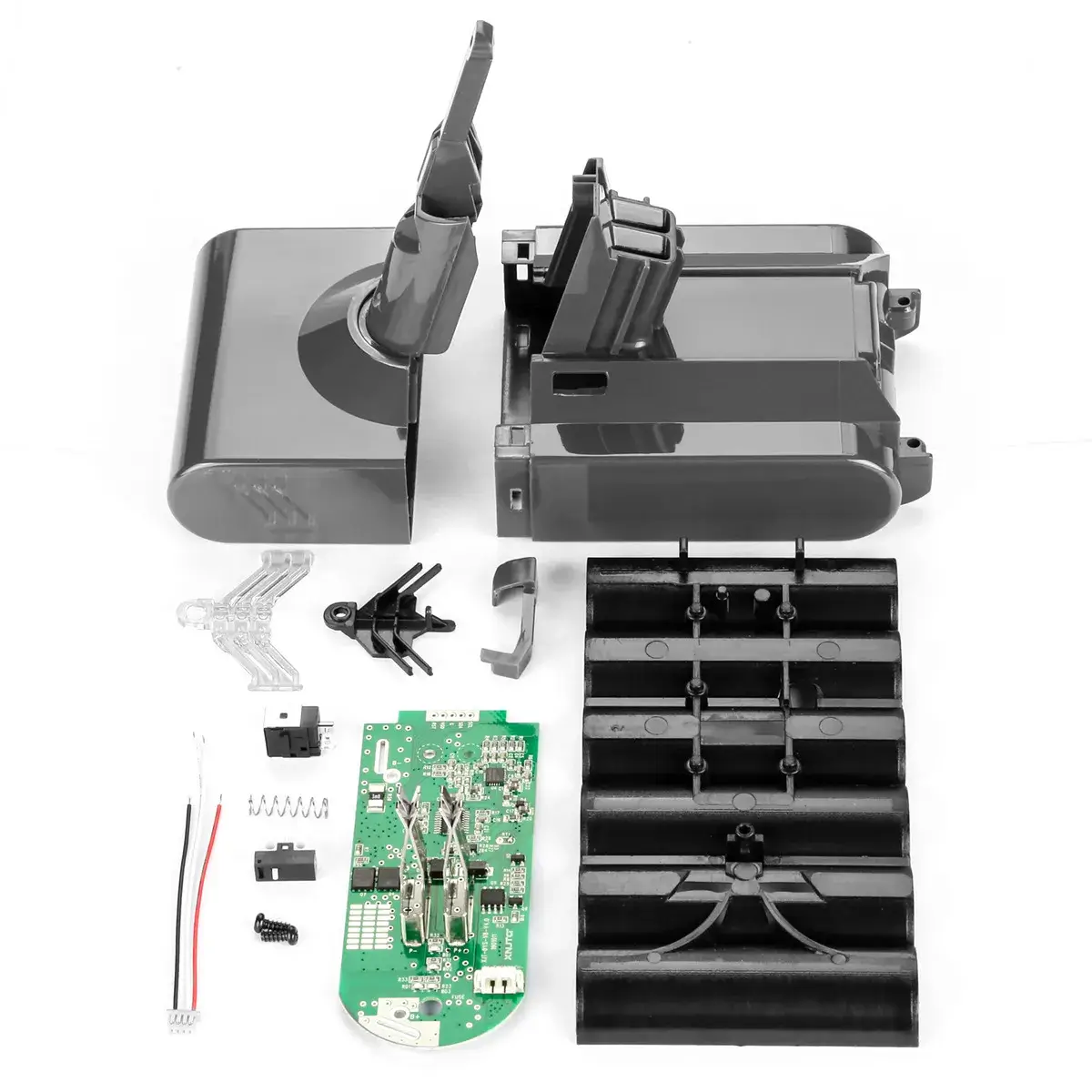
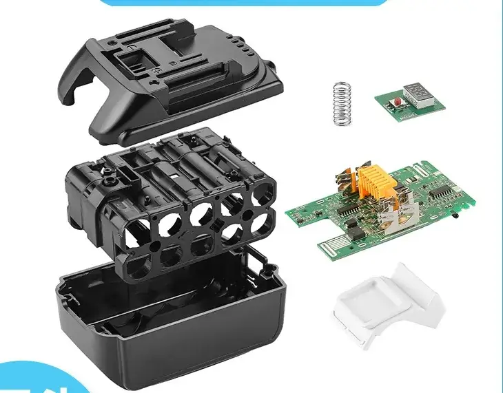
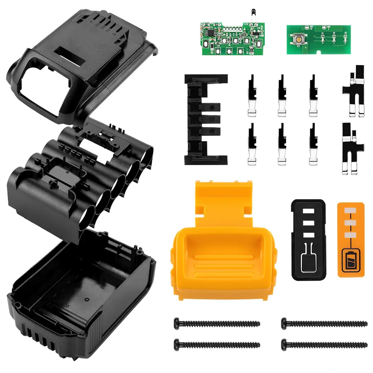
A protective PCB—often called a PCM or as part of a BMS—sits between the cell array and the pack terminals. It continuously monitors each cell’s voltage and current. When thresholds are exceeded (over‑charge, over‑discharge, or over‑current), MOSFET switches isolate the pack to prevent damage or hazards.

2. Key Functions of a Battery PCB
A proper protection circuit delivers four core safeguards:
- Over‑Charge Protection: Cuts off charging when any cell exceeds its safe maximum voltage.
- Over‑Discharge Protection: Stops discharge before any cell drops below its cutoff voltage.
- Over‑Current/Short‑Circuit Protection: Detects excessive load or short and immediately disconnects the pack.
- Cell Balancing: Passive equalization of multi‑cell packs to maintain uniform cell voltages (in PCM/BMS modules).
3. PCB vs. PCM vs. BMS: What’s the Difference?
- PCB (Protection Circuit Board): Basic voltage and current cutoff.
- PCM (Protection Circuit Module): PCB with passive balancing resistors.
- BMS (Battery Management System): Advanced module offering communication (I²C, SMBus), active cell balancing, and diagnostic functions.
Choose based on your pack complexity and monitoring needs.
4. Typical Protection Circuit Layouts
Common components in lithium battery protection designs include:
- MOSFET Switching: High‑speed FETs to connect/disconnect the pack.
- Voltage‑Sense Resistors/Dividers: Monitor each cell’s voltage.
- Current‑Sense Shunts or Hall Sensors: Measure pack current for over‑current detection.
- Passive Resistor Banks: Bleed off excess cell charge for multi‑cell balancing.
5. Technical Design Considerations
Key PCB design parameters:
- Component Selection: FETs with low R<sub>DS(on)</sub> and precision resistors minimize losses.
- PCB Layout: Reduce loop areas, include thermal vias, and ensure adequate copper thickness.
- Threshold Configuration: Hardware or firmware‑controlled cut‑off setpoints.
- Standards Compliance: Design to meet UL 2054 and IEC 62133 safety requirements.
6. Risks of No Protection Board
Operating without a PCB/BMS invites serious hazards:
- Over‑Charge → Thermal runaway and possible fire.
- Over‑Discharge → Irreversible capacity loss from copper dissolution.
- Short Circuit → High current arcs and fire risk.
- No Balancing → Cell voltage divergence, leading to premature pack failure.

7. Signs Your PCB Needs Repair or Replacement
Watch for these symptoms of PCB failure:
- Pack refuses to charge or discharge despite healthy cells.
- Intermittent connect/disconnect under load.
- Visible damage: burn marks, corrosion, or bloated components.
- Uneven cell voltages in a multi‑cell pack.
8. Troubleshooting & Repairing a Battery PCB
A step‑by‑step approach:
- Visual Inspection: Look for damaged traces, burnt parts, or swollen capacitors.
- Voltage Checks: Measure gate voltages on MOSFETs and cell tap resistors.
- Continuity Tests: Verify FET switching paths and protection resistor integrity.
- Component Replacement: Swap faulty FETs, resistors, or connectors.
- Re‑calibration: If programmable, reset voltage/current thresholds to spec.
9. Future Trends in Protection Boards
Emerging BMS technologies include:
- Active Cell Balancing: Faster and more efficient equalization using DC‑DC converters.
- Wireless Monitoring: Bluetooth or CAN bus for real‑time pack data.
- Miniaturized FET Packages: Higher current handling in smaller footprints.
- AI‑Enhanced SOC/SOH Estimation: Machine learning models for precise charge and health predictions.
10. FAQ
Q1: What is the main function of a battery PCB?
To safeguard cells by cutting off under unsafe voltage, current, or temperature conditions and provide basic passive balancing.
Q2: How often should a battery PCB be replaced?
Replace upon failure symptoms or after \~1,000 cycles if protection thresholds drift beyond specified tolerances.
Q3: How do I ensure PCB quality?
Use UL 2054/IEC 62133 certified modules, verify manufacturer markings, and review test reports.
Q4: How does a protection circuit board work?
It uses voltage and current sensing plus MOSFET switches (and balancing resistors) to disconnect or balance cells under fault or imbalance conditions.

11. Key Takeaways & Next Steps
- Recap: A robust PCB/BMS is indispensable for safe Li‑ion pack operation.
- Action Items: Source certified protection boards, monitor for failure signs, and incorporate active balancing and smart BMS features as needed.
Staying informed on protection technology ensures your battery packs remain reliable, efficient, and safe.