
Makita 18V Cell Chemistry Choices: Tradeoffs, Tests & Procurement
Selecting a chemistry for Makita-format 18V packs is a tradeoff. NMC/NCA delivers highest energy density and peak power but needs strict thermal paths and sophisticated BMS. LFP gives superior thermal stability and long cycle life but increases pack weight and requires different charge voltage/SOC approaches. LMO or blended chemistries serve high-pulse niches. Always validate vendor claims with a reproducible acceptance protocol (OCV, IR, thermal, cycle-spot tests) rather than trusting datasheets alone.
1 — Non-negotiable safety rules
If a pack is swollen, smoking, sparking or very hot, isolate it outdoors on a non-combustible surface, label QUARANTINE, and follow hazardous-waste/RMA procedures. Never puncture or open cells outside certified labs. Never bypass thermistors or BMS protections.
2 — Why cell format (18650 vs 21700) matters
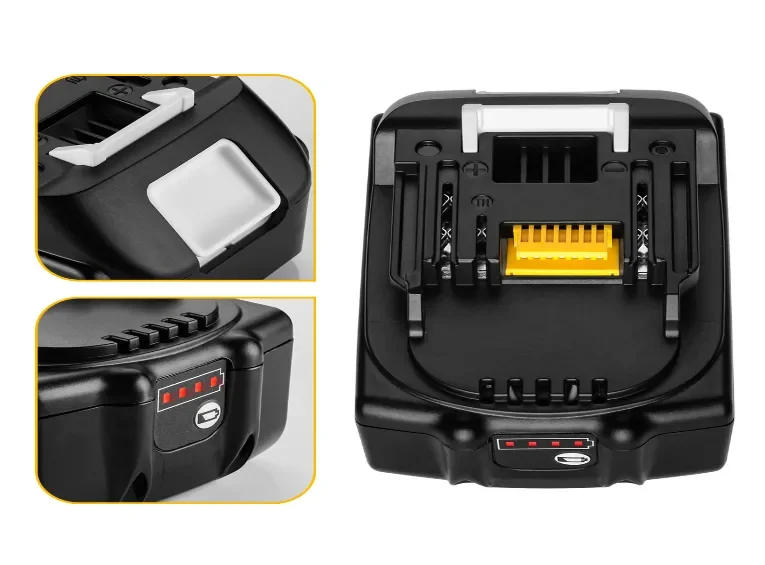
18650→21700 shift affects internal resistance, Wh per cell, thermal headroom and mechanical layout. 21700 generally gives higher Wh and lower pack IR for the same count, but changes mechanical fit and thermal pathways. For Makita 18V, typical pack OCV nominally ~18–20 V (full ~20–21.6 V); OCV <17–18 V on new lots should be treated as suspect.
3 — Quick chemistry comparison (real-world implications)
NMC / NCA — Pros: highest energy density, best for weight-sensitive pro tools and high sustained power. Cons: faster heat build-up, higher propagation risk; needs aggressive thermal design, accurate SOC/SOH, and firm firmware limits.
LFP (LiFePO₄) — Pros: excellent thermal stability, low runaway risk, very long cycle life and calendar life. Cons: lower energy density (heavier packs), different charge voltage & SOC curves, and possible cold-temperature penalties.
LMO / hybrids — Pros: high pulse capability and low internal resistance for short bursts. Cons: aging behavior varies; many blends require duty-cycle validation.
4 — Metrics buyers must measure (not guess)
Measure these under your duty profile: Wh/kg (runtime), pack & per-cell internal resistance (IR), voltage sag at startup and sustained load, peak & sustained C-rate capability, thermal rise across duty cycles, cycle-life retention curves (sampled at 0/100/300 cycles), cold/hot charge acceptance, and propagation/venting behavior. Demand raw logs.
5 — How chemistry changes BMS, thermistor and charger behavior
Chemistry determines top-end voltages, balancing strategy and SOC estimation. LFP has a flatter voltage curve and lower charge endpoint (~3.6–3.65 V/cell) requiring different SOC models; NMC requires tight top-end cutoffs. Ensure vendors supply thermistor curve files, BMS event logs, charger handshake specifications and OTA/firmware policies.
6 — Reproducible acceptance test protocol
A. Field / incoming inspection
-
Visual: seal, vents, swelling.
-
Resting OCV after 30 min idle.
-
IR pulse: 10 s at rated discharge; record ΔV and calculated IR.
-
Thermal snapshot during a representative duty cycle.
B. Bench integration
-
Charger insertion: start-current snapshot (first 30 s).
-
Time-to-80% and 100% under buyer’s charger and defined ambient.
-
30-minute sustained discharge or representative tool cycle with per-cell surface ΔT logging.
-
Startup/impact sag test (e.g., stall/impact drill load).
C. Cycle-spot & endurance
-
0/100/300 cycle spot tests: log Ah retention and IR trend.
-
Target: ≥80% capacity at 300 cycles for high-end NMC claims (adjust by vendor promise). LFP should materially exceed NMC here.
-
Require UN38.3 and independent propagation/abuse test reports.
D. Evidence to collect
-
Raw charge/discharge logs, per-cell voltages, IR traces, thermographic sequences, BMS event logs and firmware versions.
7 — Which chemistry fits which use case?
-
High-power, weight-sensitive pro tools: NMC/NCA with strict thermal and BMS regimes.
-
High-cycle fleets, rentals, safety-critical sites: LFP — accept weight penalty for safety and lifecycle.
-
Short-burst, very high pulse loads: LMO or hybrids — validate aging and thermal behaviors carefully.
8 — Field SOPs to prolong pack life
-
Store at ~40–60% SOC for long-term storage.
-
Allow packs to cool to room temp before charging after heavy use.
-
Warm packs before charging in cold environments.
-
Rotate spares and track per-pack IR growth and swelling.
-
Use verified chargers only; replace packs showing abnormal sag or ΔT.
9 — Quick FAQ
Is LFP always safer? LFP is significantly more thermally stable, but pack mechanical design, venting and BMS still govern real-world safety.
Will switching chemistry break chargers? Possibly — charge voltages and thermistor mapping differ; validate integration.