
Makita Charger PCB Failures: Symptoms, Diagnosis & Repair Costs
Makita-style smart chargers are SMPS-based. The most common PCB failures are aged electrolytic capacitors, blown fuses/surge parts, failed rectifiers/MOSFETs, corroded contacts and cracked solder joints. Some fixes are inexpensive; major SMPS or transformer damage is usually uneconomic — replacement is often the safer choice. Below is a practical, safety-first guide you can use immediately.
Safety first — read this before opening anything
-
Chargers contain lethal mains voltages and electrolytic capacitors that can hold dangerous charge even after unplugging.
-
Do NOT open or work on a charger unless you know HV safety procedures, how to safely discharge capacitors, and you have appropriate PPE and tools.
-
If the unit smokes, emits a burning smell, or has melted plastic — unplug and do not attempt DIY repair. Send it to a qualified repair shop or replace the unit.
-
If you are comfortable with electronics, still follow isolation-transformer procedures and verify caps are discharged before touching anything.
1 — Most common PCB failure modes & symptoms
-
Aged / bulging electrolytic capacitors
Symptoms: Charger powers on but output is unstable, charging is very slow, audible SMPS whine, or unit dies under load. -
Blown primary fuse / surge protection parts (MOV, TVS)
Symptoms: Charger dead (no LEDs), scorch marks or visible surge damage near mains input. -
Failed bridge rectifier / Schottky diodes
Symptoms: No DC available on the secondary — SMPS won’t produce output though mains side may look OK. -
Failed switching MOSFET or SMPS controller IC
Symptoms: Little/no switching activity; sometimes humming or immediate dead output; burnt smell may be present. -
Faulty feedback/regulation parts (optocoupler, TL431)
Symptoms: Charger runs but never reaches correct output voltage or shuts off prematurely. -
Thermistor / temperature-sense circuit failure
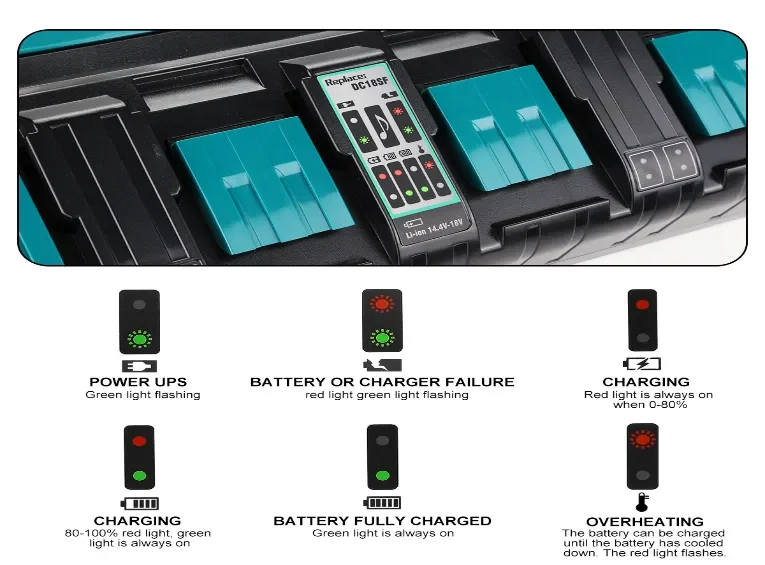
Symptoms: Charger constantly reports a temperature fault and refuses to charge (LED temp/error pattern). -
Battery-contact springs / connector corrosion
Symptoms: Intermittent charging, arcing, LEDs flicker when battery is seated. -
Cracked solder joints (thermal/vibration stress)
Symptoms: Intermittent faults that sometimes “work if tapped,” then fail. -
Burnt PCB traces or damaged transformer
Symptoms: Visible burn marks, heavy smoke smell — often uneconomic to repair.
2 — Simple, safe checks you can do (power OFF / unplugged first)
-
Visual inspection: Look for bulging caps, scorch marks, lifted traces, cracked solder, or broken springs.
-
Fuse check: With power removed, check mains fuse continuity. A blown fuse is a symptom — not necessarily the root cause.
-
Contacts: Clean the charger bay and battery rails with isopropyl alcohol; reseat the battery.
-
Smell test: A burnt-electronics odor usually indicates a major failure — plan to replace.
Do not probe live mains circuitry unless you have the right isolation gear and training.
3 — What a pro shop will test (technician diagnostics)
A competent repair shop typically follows this procedure:
-
Verify mains fuse, MOV/TVS, and input components.
-
Diode/rectifier checks (DC rails).
-
ESR and capacitance testing of electrolytics (ESR meter) — high ESR = replace caps.
-
Microscope inspection for cracked or cold solder joints; reflow as needed.
-
Power-up from an isolation transformer and check switching-node waveforms with an oscilloscope.
-
Verify feedback loop (optocoupler/TL431) and current-sense circuits.
-
Swap/replace suspect MOSFETs or controller ICs if equivalents are available.
-
Functional test with a known-good battery and thermal monitoring.
4 — Typical repair actions
-
Replace bulging or high-ESR electrolytic capacitors (primary & secondary).
-
Replace bridge rectifier, Schottky diodes, mains fuse, MOVs/TVS.
-
Replace MOSFET(s) or SMPS controller IC (requires correct equivalents).
-
Replace optocoupler/TL431 components in feedback loop.
-
Reflow or re-solder cracked joints; replace weak springs or contact pads.
-
Transformer or heavily burnt PCB — usually replace the whole charger.
5 — Realistic cost ranges (professional bench repair, USD)
These are ballpark ranges; actual prices depend on region, part availability and shop hourly rates.
| Severity | Typical examples | Parts | Labor (estimate) | Total (approx.) |
|---|---|---|---|---|
| Minor | Replace blown fuse, clean contacts, 1–4 small caps, reflow | $2–$25 | $25–$75 | $30–$100 |
| Moderate | Bridge rectifier, optocoupler/TL431, 1–2 MOSFETs, multiple caps | $10–$60 | $60–$150 (SMT skills) | $70–$210 |
| Major | Transformer replacement, multiple IC swaps, trace repairs | $25–$150+ | $100–$300+ | $125–$450+ |
| Severe | Burnt PCB/transformer/structural damage — parts scarce | Parts high | Labor high | Often uneconomic — replace |
Rule of thumb: if a repair quote is >50% of the cost of a new OEM charger, replacement usually wins.
6 — Typical turnaround times
-
Minor repairs: same day → 48 hours.
-
Moderate repairs: 2 → 5 business days (parts sourcing may add time).
-
Major repairs: 5 → 14+ days (transformer or rare ICs may delay).
7 — Repair vs Replace — realistic decision matrix
Repair if:
-
Diagnostic points to caps, diodes, fuse, springs or a small number of replaceable SMT parts; AND
-
Quoted repair cost is < ~50% of a new OEM or high-quality aftermarket charger.
Replace if:
-
Transformer or heavy PCB burns exist; OR
-
Repair quote approaches replacement cost; OR
-
You need reliable, warranted service without risk of cascading failures.
Warranty note: If the charger is under manufacturer warranty — return to the maker. Do not open the unit.
8 — How to keep repair costs low
-
Try non-invasive fixes first: clean contacts, check outlet, confirm battery health.
-
Collect multiple failed units and drop off for bulk bench time (shops often give discounts).
-
Use shops that specialize in power supplies / SMPS repairs.
-
Ask for a diagnostic-only quote before authorizing parts/labor.
-
If you decide to DIY and you are experienced, source higher-quality replacement capacitors (low-ESR) and matching parts.
9 — Preventive tips to extend charger PCB life
-
Keep chargers ventilated and dust-free; avoid stacking them.
-
Clean battery rails periodically with isopropyl alcohol.
-
Avoid charging in extreme heat; let packs cool before charging after heavy use.
-
Use surge protection / surge-protected circuits on jobsites.
-
Rotate chargers if you run heavy throughput — give SMPS units periodic rest.
10 — Quick symptom → likely cause cheat-sheet
-
Dead (no LED): blown mains fuse, failed input rectifier, or failed SMPS controller.
-
Powers but no output / very slow charge: likely bulging caps or secondary rectifier failure.
-
Burnt smell / visible scorch: major component failure — likely replace.
-
Constant temp/cold fault: thermistor / temp-sense circuit fault.
-
Intermittent on/off: cracked solder joints or corroded contacts.
Bottom line
Many Makita-style charger faults are inexpensive fixes (caps, diodes, fuses, springs). But transformer damage, burned SMPS ICs, or major PCB burns are typically uneconomic to repair — buying a new, safety-certified charger is usually the smarter, safer choice. Use the quick inspection checklist above to triage, get a diagnostic-only quote from a reputable shop, and replace when repair costs approach the price of a new charger.