
Makita Packs: Reverse-Polarity and Mechanical Keying — Design Notes
Explain the importance of mechanical keying and reverse-polarity protection in Makita-style packs, summarize common electrical and mechanical protection strategies, outline failure patterns, and provide reproducible inspection/testing workflows plus procurement acceptance requirements so designers, technicians, and buyers can verify safety and compatibility.
1. Audience & Purpose
This guide is written for pack designers, BMS/firmware engineers, repair technicians, aftermarket suppliers, and procurement teams. It provides a field and bench inspection checklist, required mechanical documentation (CAD + tolerances), electrical protection requirements, and a clear go/no-go list for purchasing decisions.
2. Safety First (Must-Read)
Strict caution: avoid operating or testing packs that are hot, swollen, punctured, or visibly damaged. Never bypass polarity protection. Board-level testing requires current-limited supplies, temperature monitoring, ESD control, and qualified personnel.
3. Why Polarity & Keying Matter (Practical View)
Mechanical keying ensures the pack inserts in the correct orientation, maintains proper terminal sequencing (thermistor and sense pins first), and reduces mis-mating risks. Reverse-polarity protection prevents destructive shorts that can damage both tool electronics and chargers.
4. Common Reverse-Polarity Protection Methods (Hardware & Firmware)
-
Back-to-back MOSFETs: Low loss, resettable, widely used in modern packs.
-
Ideal-diode/OR-controllers: Controlled conduction, minimal drop, higher cost/complexity.
-
Series diode: Simple but high loss; rarely suitable for high-power tools.
-
Crowbar + fuse (comparator-triggered): Sacrificial, single-use; protects the system by intentionally destroying the pack.
-
Mechanical interlocks & staggered pin sequencing: Prevent incorrect insertion at the physical connector level.
Also compares resettable vs sacrificial designs, voltage-drop and heating implications, and suitability at different price points.
5. Typical Mechanical Keying Patterns (and Implications)
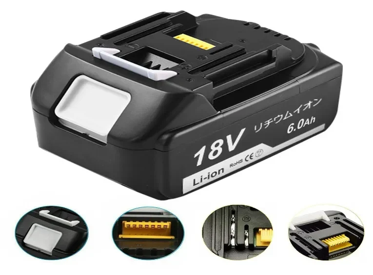
Makita-style packs commonly use asymmetric rails, indexing ribs, dual-plane latch geometry, and staggered contact lengths that ensure make-first/break-last sequencing. Some keying styles intentionally reinforce OEM exclusivity, while others support safe third-party compatibility.
6. Failure Modes & Real Risks
Typical problems include worn or broken key rails causing misalignment, latch fatigue leading to partial seating, absence of MOSFET polarity protection causing catastrophic reverse insertion, poor plating or corrosion causing hotspots, and “forced-fit” insertion damaging both mechanical and electrical interfaces.
7. Reproducible Inspection & Test Protocol (Field → Bench)
Field checks: Inspect key geometry, verify latch engagement, confirm OCV polarity, conduct controlled swap tests.
Bench checks: Validate staggered pin-sequencing with a probe, measure contact resistance under specified clamp force (mΩ level), simulate reverse polarity using a current-limited supply, and run specified cycles of insertion/removal.
Lab checks: Perform destructive I²t/let-through analysis on protection components.
Pass/fail criteria must define allowable mΩ ranges, latch-force minimums, polarity tolerance, and acceptable thermal rise.
8. Acceptance & Procurement Checklist
Procurement should require:
-
CAD drawings with full tolerances for rails, ribs, latch geometry
-
Pinout + pin-length sequencing
-
Declared polarity-protection method with I²t or MOSFET SOA data
-
Contact-resistance logs for golden units & samples
-
Endurance-cycle test reports
-
Golden reference samples for QC
-
UN38.3 certification and clear RMA terms for protection-related failures
9. Field SOPs & Operator Rules (Reduce Incidents)
Operators should inspect key geometry and terminals before use, avoid forced insertion, compare packs with golden references, retire units with repeated mechanical faults, and log serial numbers for traceability.
10. Repair vs Replace Decision Rules
Replace packs with cracked latches, warped terminal housings, or out-of-spec contact resistance. Repair only when modular parts are available, documented procedures exist, and the safety/liability cost is acceptable.
11. Quick Test Matrix
A concise test matrix including mechanical-seating checks, contact-resistance measurement, reverse-insertion simulation, pin-sequencing validation, and endurance-cycle tests, with specific methods and pass thresholds.