Why does the battery's BMS suddenly fail?
A Battery Management System (BMS) safeguards rechargeable packs by monitoring cell voltages, balancing charge, preventing over-current/over-temperature, and communicating with chargers and devices. When the BMS fails, your pack can lose capacity unexpectedly, shut down tools without warning, or even pose safety risks like thermal runaway. Below, we dive into the main failure modes, real-world triggers, and actionable prevention strategies.

A Battery Management System (BMS) can abruptly stop working when one or more of its critical monitoring or protection functions is overwhelmed or compromised. Common triggers include: an internal short or cell failure that trips the BMS’s over‑current or over‑discharge circuit faster than it can rebalance voltages; extreme heat—either from prolonged high‑current draw or ambient temperature spikes—that damages the BMS’s semiconductor switches or temperature sensors; moisture ingress or corrosion at weld joints and connector pins that breaks communication between the controller and individual cell stacks; and firmware or calibration drift after many cycles, which causes the BMS’s voltage‑threshold comparators to misinterpret normal fluctuations as faults. Mechanical shock or vibration can crack sensor solder joints or flex PCBs, instantly severing the BMS’s ability to regulate. Once any of these subsystems fails, the BMS will refuse to energize the pack to protect cells and prevent unsafe conditions. In practice, a sudden, unresettable BMS fault almost always indicates either irreversible cell damage or hardware failure within the BMS electronics, necessitating pack replacement or professional board‑level repair.
Core Functions of a Healthy BMS
A robust BMS ensures:
| Function | Purpose |
| Cell voltage monitoring & balancing | Keeps all cells within safe voltage; equalizes cells via passive bleed |
| Over‑charge/discharge protection | Isolates pack when any cell drifts out of safe range |
| Over‑current/short‑circuit safeguards | Cuts output during spikes or shorts |
| Thermal regulation | Throttles operation when sensors detect high temperatures |
| Communication handshake | Coordinates with chargers and devices over SMBus, CAN, or UART |
1. Electrical Stress & Overload
Failure Mode: MOSFET burnout, fuse or trace melting, voltage regulator latch‑up.
Triggers: Locked‑rotor tool currents, wiring faults, voltage transients.
| Trigger | Impact | Prevention |
| Excessive current | MOSFET destruction, blown fuses | Specify MOSFETs/fuses ≥150% peak; add slow‑blow fuses |
| Voltage spikes | Gate‑oxide breakdown, regulator latch‑up | Install TVS diodes, RC snubbers; choose high‑transient components |
2. Thermal Stress
Failure Mode: Solder joint fatigue, capacitor drying, semiconductor drift.
Trigger: Poor heat sinking, prolonged high‑load use.
| Cause | Consequence | Mitigation |
| Over‑temperature spikes | Component breakdown, erratic behavior | Use components rated ≥70 °C; add copper pours, thermal vias, small heatsinks |
| Inadequate dissipation | Shortened lifespan of ICs and caps | Optimize PCB layout for airflow; add heatsinks on MOSFETs |

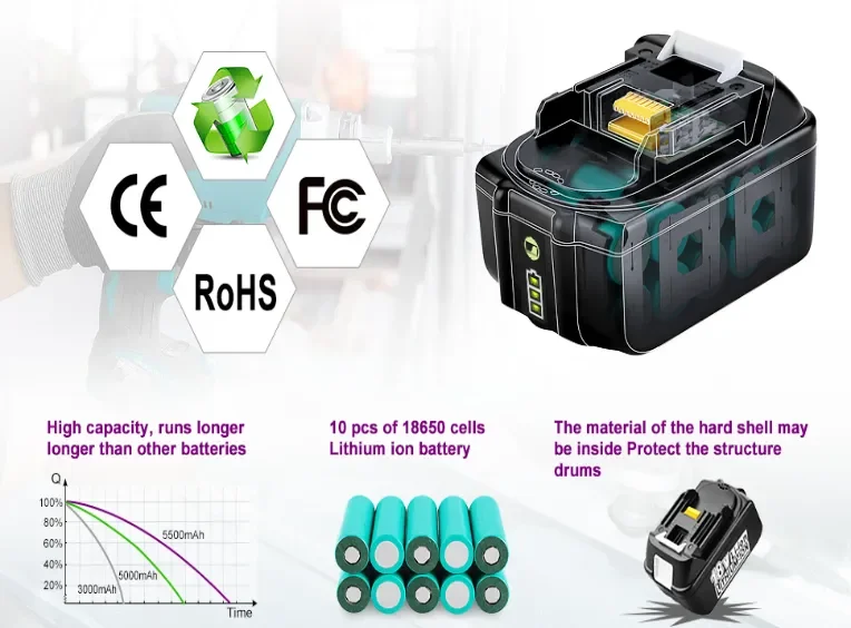
MAK-18V-LI-10 Lithium‑Ion Battery For Makita LXT Power Tools BL1860B
3. Design & Manufacturing Flaws
Design and manufacturing flaws can silently undermine a BMS long before it ever sees a charging cycle. Inadequate circuit board layout—such as traces that are too thin for peak current, poorly placed thermal vias, or insufficient creepage distances—can cause localized overheating, solder‑joint fatigue, and eventual open circuits under normal load. Using substandard MOSFETs or capacitors that lack proper voltage or temperature ratings invites premature failure: parts operating at the edge of their limits will drift out of tolerance, corrupting cell‑voltage readings or disabling the protection switches. In many budget packs, cell groups are matched only by capacity, not by internal resistance or self‑discharge characteristics, so the BMS must continually rebalance wildly divergent cells—overworking its resistive bleed circuits until they overheat or blow. Automated assembly shortcuts, like cold solder joints or insufficient ultrasonic wire bonds, create microcracks that grow under vibration and thermal cycling, severing critical sensor or ground connections. Even the choice of enclosure material matters: housings that flex under impact can stress board mounting points, while poor potting compounds allow moisture ingress, corroding connectors and sensors. Together, these design oversights and manufacturing variances erode a BMS’s ability to monitor and protect its cells, turning what should be a robust safety net into a single point of catastrophic failure.
Under‑spec parts and PCB defects lead to early‑life breakdowns.
- Under‑rated components (wrong voltage/current specs) ➔ select parts ≥120% of max ratings, apply derating
- PCB/solder defects (cold joints, thin traces) ▶ follow IPC‑610, use ≥2 oz copper for power layers, add fillets
4. Environmental & Mechanical Factors
Real‑world exposure to vibration, moisture, and debris can sever or corrode connections.
| Stressor | Failure Impact | Countermeasure |
| Vibration/shock | Fractured traces, loose connectors | Conformal coating, potting, shock‑absorbing mounts |
| Moisture/corrosion | Shorted traces, oxidized components | IP‑rated coatings, sealed enclosures, drainage features |
5. Aging & Cell Imbalance
As lithium‑ion cells age, variations in capacity, resistance, and self‑discharge between parallel groups force the BMS to balance voltages more aggressively. It bleeds current from stronger cells via resistive circuits, generating heat and stressing components until thermal or current limits are reached. Widening voltage imbalances trigger over‑/under‑voltage protection, locking the system and causing BMS failures that require pack replacement or professional reconditioning.
Over many cycles, slight cell discrepancies force early BMS cut‑offs.
- Capacity drift & passive limits ▶ use active balancing on large packs; replace electrolytics based on hours of
- Component wear‑out ▶ monitor ESR of capacitors/transistors; schedule preventive replacements
6. Firmware & Communication Errors
Firmware glitches and communication failures can disable a BMS with healthy cells. Digital buses (SMBus, I²C, CAN) relay cell data. Corrupted firmware—via bad updates, flash errors, or EMI—misreads data as faults and locks the pack. Damaged traces, loose bonds, or poor solder cause checksum errors or timeouts. Calibration drift or flash fatigue misfires comparators. When digital subsystems fail, the BMS won’t energize and can’t be fixed by power‑cycling or cleaning.
Software bugs and bus faults can leave the BMS "blind."
- Firmware bugs (SoC miscalc, watchdog failure) ▶ implement OTA updates with rollback, isolate safety tasks on dedicated core
- Bus errors (CRC failures, collisions) ▶ use differential transceivers, EMI filters, auto‑retry logic
7. External Misuse
Mechanical abuse, improper charging, and extreme environments can overwhelm a BMS, causing sudden pack failure. Impacts may crack casings or PCB traces, severing sensors. Cheap or incompatible chargers can over‑voltage or over‑current cells, tripping protection. Moisture corrodes welds and connectors, creating shorts or opens. Operating below 0 °C or above 45 °C degrades components until the BMS locks out. Even hot storage or debris bridging contacts can force permanent faults—misuse, not design, triggers these failures.
Wrong chargers or storage can pre‑trip BMS protections.
- Incompatible chargers ▶ always use certified chargers matching BMS handshake and voltage profile
- Poor storage ▶ store at 40–60% SoC, 10 °C–25 °C; top‑up every 2–3 months

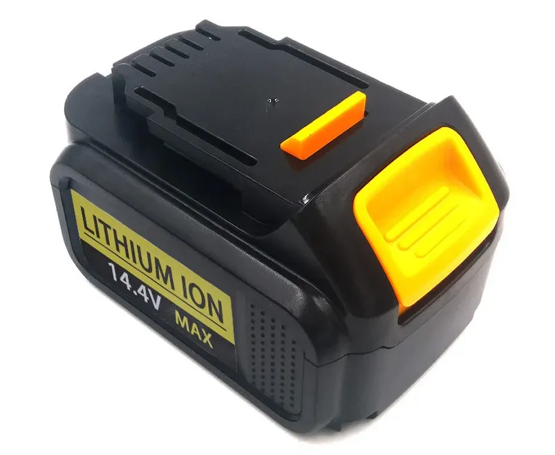
DEW-14V4-LI Replacement 12V Battery for Dewalt tools compatible with Multiple models
Best Practices to Prevent BMS Failures
- Design robustness: Over‑rate parts, include active balancing, plan thermal management.
- Manufacturing quality: Follow IPC‑610, cycle test, apply conformal coats.
- User maintenance: Use correct chargers, control storage conditions, update firmware.
Conclusion
BMS failures arise from electrical overload, thermal stress, design flaws, environmental abuse, aging, firmware bugs, and misuse. By addressing these root causes—through robust design, quality manufacturing, and diligent maintenance—you can extend pack life, enhance safety, and avoid costly downtime.